Scrapwork: PocketCHIP
Trying to replace the CHIP in PocketCHIP with a Raspberry Pi 4B.
This post describes the process I followed instead of the end result. This means that my descriptions and assessments may be incorrect or very sparse, especially in the beginning. Most of the information is fleshed out later. If you are not interested in this process, jump to the TL;DR.
Some time ago I remembered that I had this stashed away in a drawer:
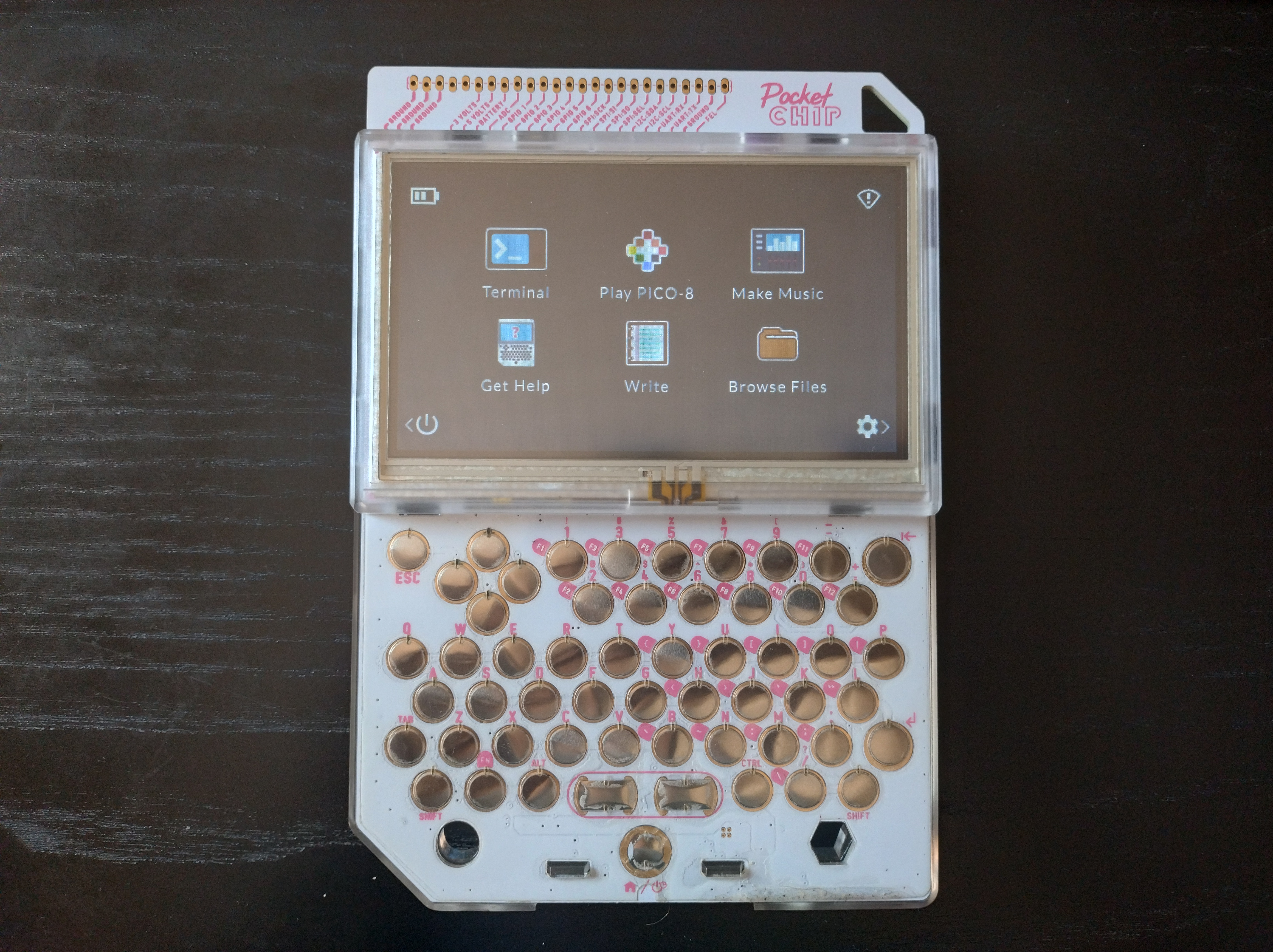
It’s a PocketCHIP, a Linux handheld computer created by Next Thing Co. (NTC) in 2015. The venture was kicked off with a Kickstarter campaign that raised $2.000.000, 40 times its target amount, with close to 40.000 backers. I was one of them, and after waiting about a year, I received my PocketCHIP.
I had a very good time using it on and off for the next few years, but unfortunately NTC entered insolvency in 2019. Of course, that meant no more official software updates. The tooling, especially for flashing the device, slowly became obsolete, and the documentation was eventually taken down. There have been community efforts to keep the CHIP usable, to the point where it can flashed and used as it was in 2018. There are also guides regarding how to update the operating system to a more recent version. However, the kernel has stayed the same, so security and compatibility issues will most likely keep appearing.
In my case this meant I stopped using the PocketCHIP altogether. I liked the form factor though, so when I found it again I wondered if I would be able to scrap it and make something similar, but maybe more durable (software-wise), functional and maintainable.
So in summary, the goal I decided on was to make something functionally similar to the PocketCHIP. If possible, I wanted to reuse the existing components without introducing anything new (except for the single-board computer, or SBC, replacement). This post is about tearing apart the PocketCHIP and seeing ways to reuse its components to achieve the aforementioned goal.
I have a Raspberry Pi 4 model B available, so I used it to test and prototype. Hopefully it will be part of the final product as well, but there are some challenges regarding its integration with PocketCHIP. Since I’m going to mention it a lot, I’m abbreviating Raspberry Pi to RPi, and model 4B specifically to RPi4B.
Available components
I started by disassembling the PocketCHIP and taking stock of what I was working with.
CHIP
NTC’s $9 computer. It’s the core of the PocketCHIP and the main component to replace.
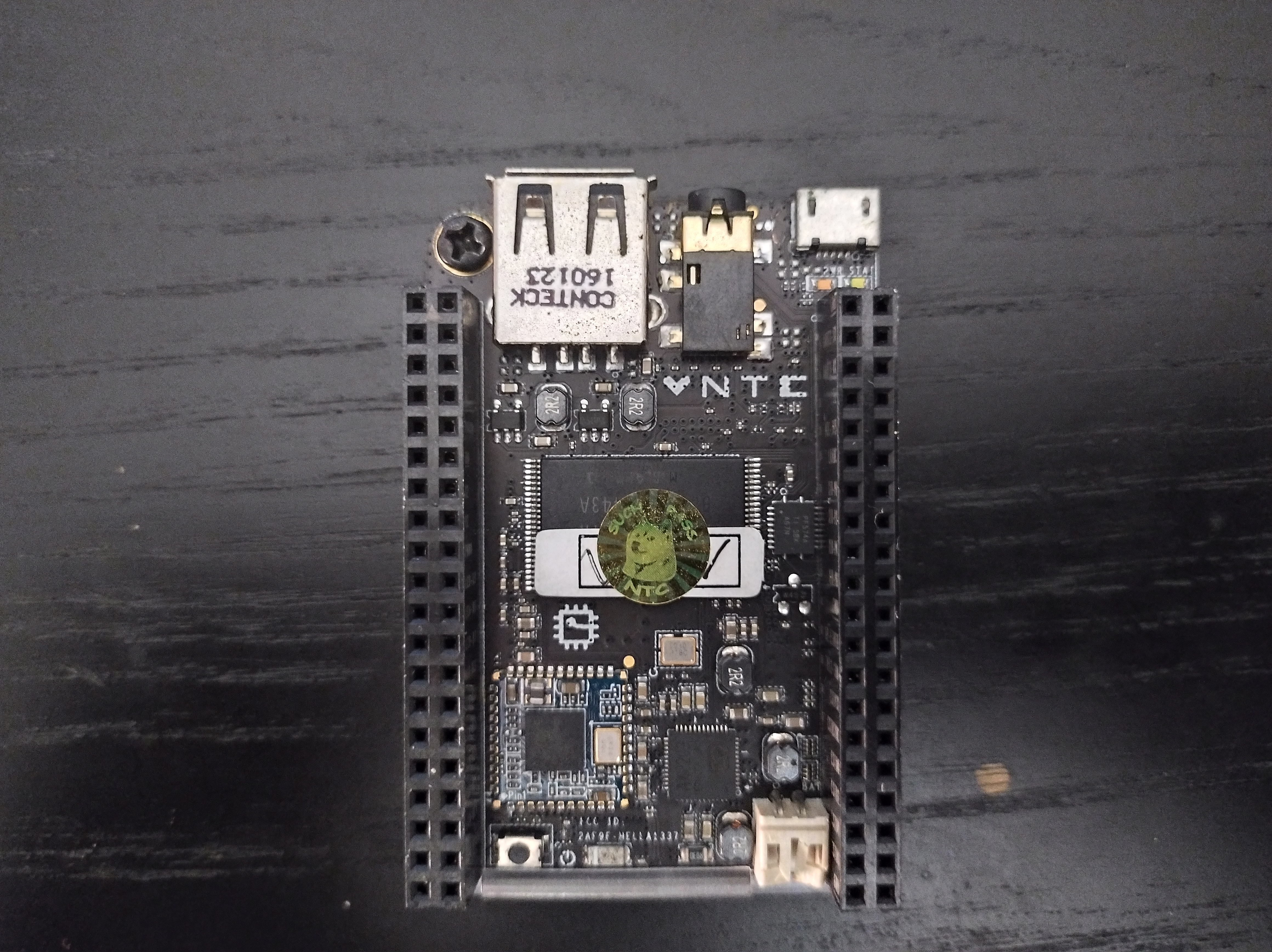
The CHIP has built-in battery management, which is uncommon in other SBCs. This is something we will have to account for if we want the final product to be portable.
3.7V LiPo battery
PocketCHIP runs on this battery. According to the docs it lasts about five hours.
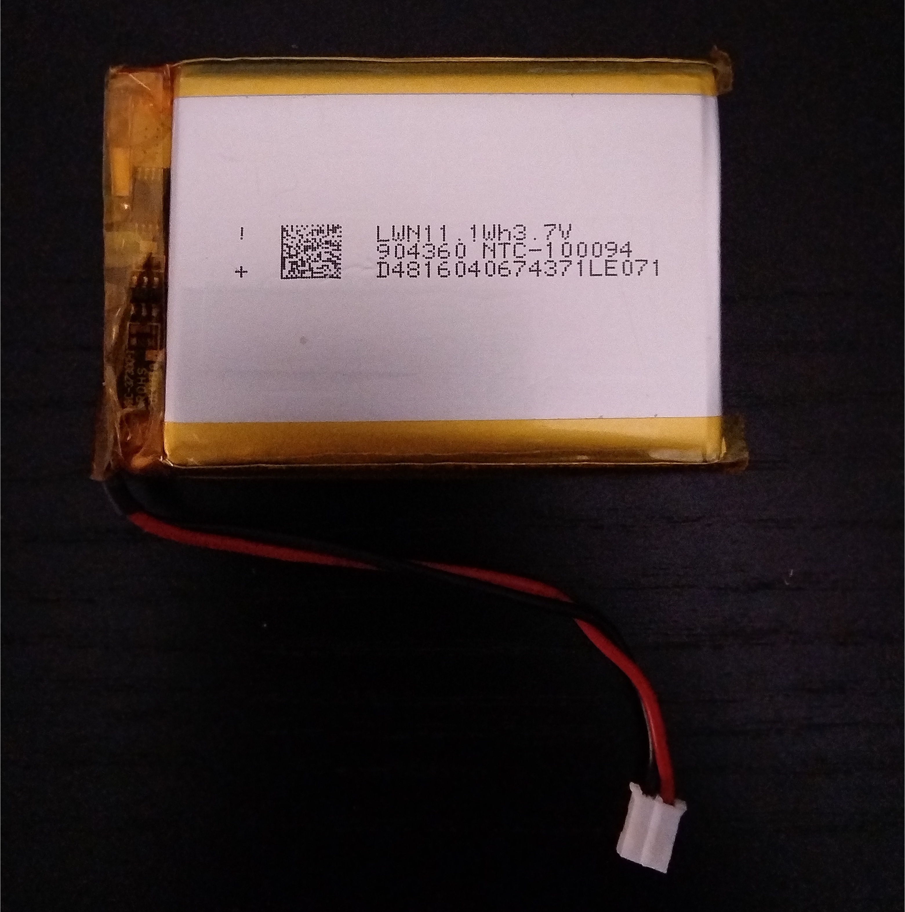
Given the battery has 11.1Wh and 3.7V, we can determine the capacity to be \(\frac{11.1Wh}{3.7V}=3Ah=3000mAh\).
On the other hand, RPis require a 5.1V supply. This means a DC-DC boost converter is needed to use the same battery. A Power Supply Unit capacity of 3A is recommended for RPi4B, but the current draw is usually less than one amp unless the device is under stress. I’m going to assume one amp as the average current draw since I wouldn’t frequently run heavy workloads on the RPi, but I would have at least the display to provide power to.
We can calculate the current draw from the battery by equating the power from the battery with the RPi’s consumption. Given \(V_{in}\), \(I_{in}\) and \(P_{in}\) as the parameters that the battery inputs into the circuit; \(V_{out}\), \(I_{out}\) and \(P_{out}\) as the consumption of the RPi from the circuit, and \(E\) as the efficiency factor of the converter:
\[V_{in}=3.7V \\ V_{out} = 5.1V \\ I_{out} = 1A\] \[P_{in} = V_{in} * I_{in} = 3.7 * I_{in}\] \[P_{out} = P_{in} * E = 3.7 * I_{in} * E \\ P_{out} = V_{out} * I_{out} = 5.1 * 1 = 5.1W \\ 5.1 = 3.7 * I_{in} * E\] \[I_{in} = \frac{5.1}{3.7} \frac{1}{E} = \frac{1.38}{E}\]Assuming an efficiency of 100% the draw from the battery would be \(1.38A\), so the battery would last \(\frac{3Ah}{1.38A} = 2.17h\). At 90% the draw would be \(1.53A\); the battery life would be reduced to \(\frac{3Ah}{1.53A} = 1.95h\). About two hours of battery life is not at all enough for a portable device, so I’d need another battery (and then I could omit the converter as well). A Pi Zero instead of a 4B would considerably reduce current draw, but it wouldn’t probably perform well enough as a handheld Linux device.
Touchscreen
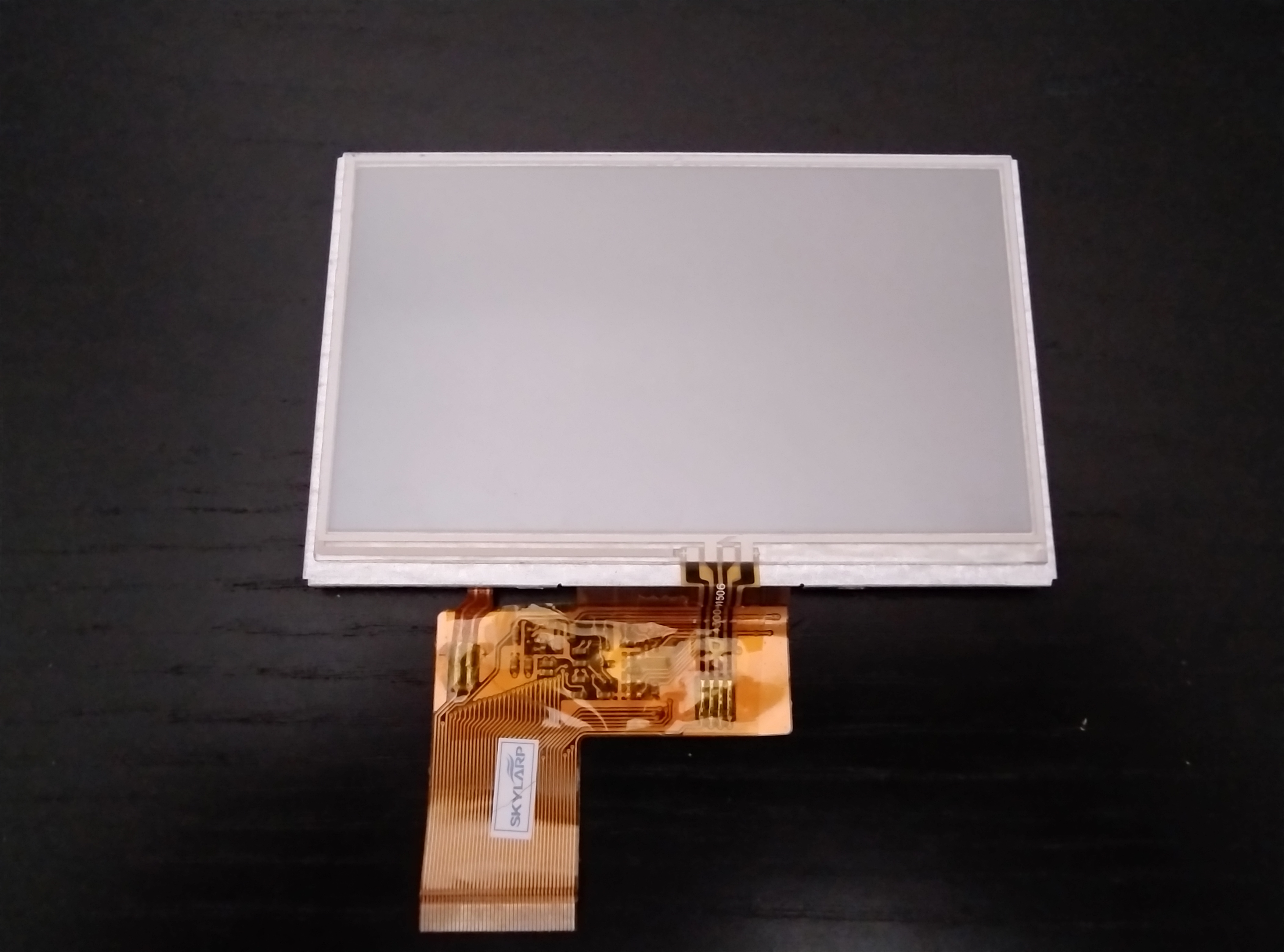
A 4.3” TFT LCD. It connects to the board through a 20mm wide, 40 pin ribbon cable. I remember that the original display broke and I replaced it with this one, but I don’t remember where I bought it, nor what criteria I used to select the new model.
The numbers on the back led me to spec pages like this one, and also a preliminary datasheet. I wasn’t sure if I could trust a random datasheet from the internet though.
Board and case
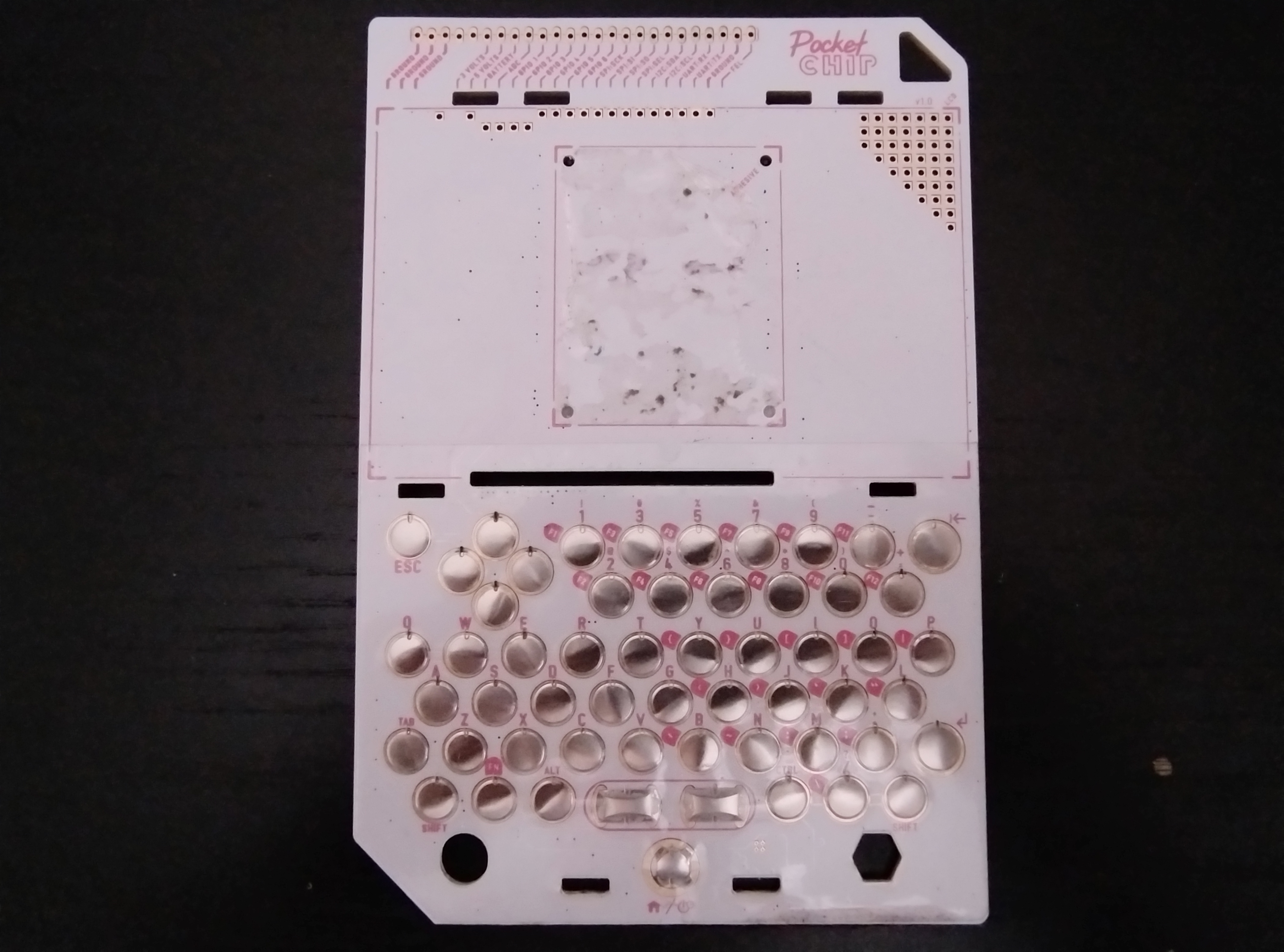
The core of the PocketCHIP is this printed circuit board. On the front are a keyboard and the screen’s mountpoint, as well as a set of GPIO slots at the top:
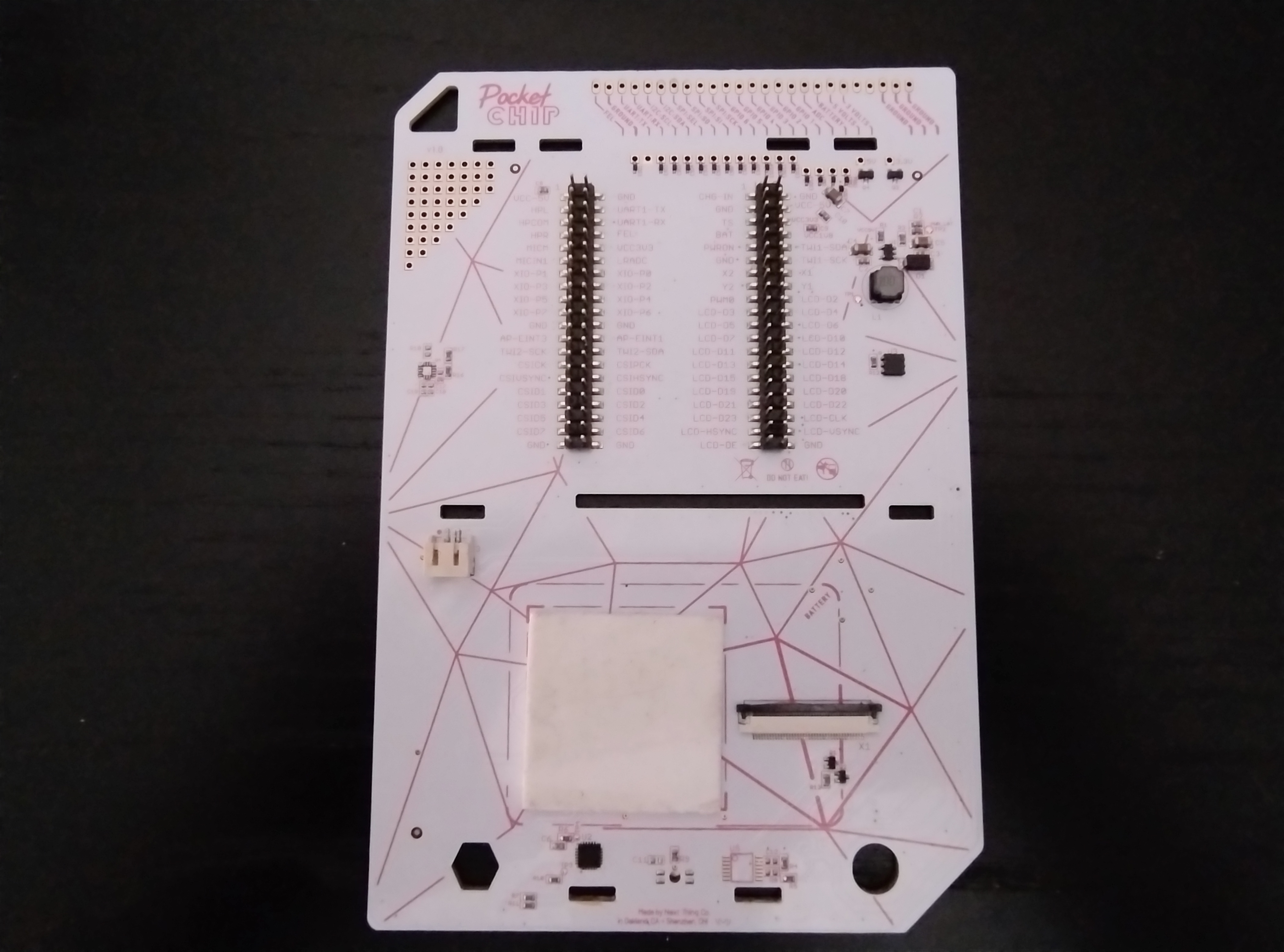
The back is where the battery and CHIP interface. The latter is inserted into the pins, which hold it in place. Each pin is labelled according to its function:
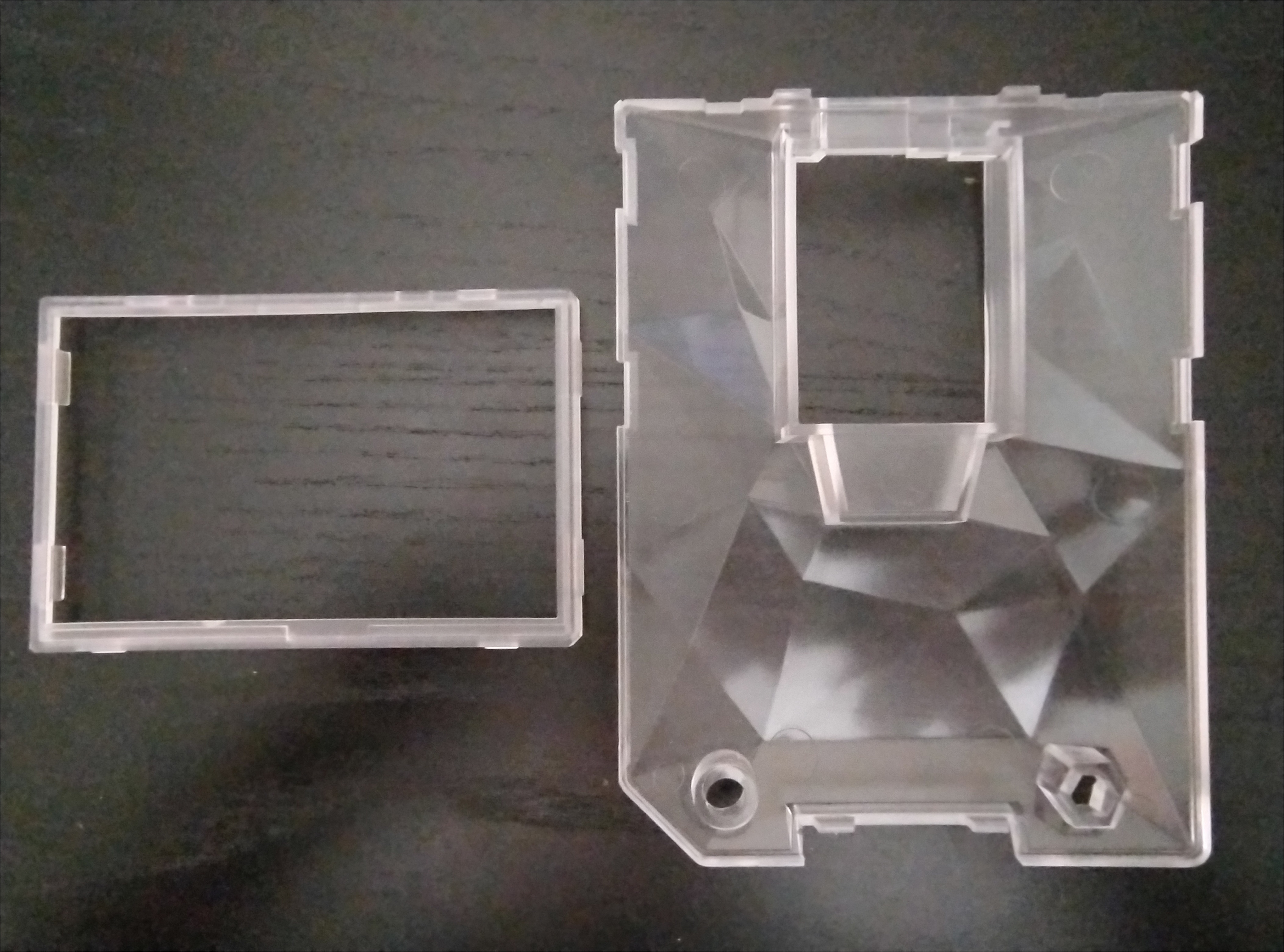
The battery and screen are held in place by a plastic casing that snaps onto the board:
It would have been interesting if I could have re-used these two parts. However, the pinout doesn’t match the RPis’, so I would’ve needed to use cables or a perfboard to map one to the other. My RPi4B also didn’t fit into the CHIP’s slot in the case, so the end result wouldn’t have been as compact. Additionally, the PocketCHIP’s keyboard is quite uncomfortable to use, and if I’m going to carry an external one with me there’s no point in making the built-in one functional either. So the only thing to consider from the board is that it has very accessible GPIO, something I might want to carry over to a new design.
If I decide to design my own handheld device I could reuse at least the screen. There’s a 16mm DSI port on RPi4B, but the screen’s ribbon cable is 20mm. However, reading the documentation it should be possible to connect the display to GPIO and control it from there. There are breakouts for this.
But does the display just work with RPis? I have no clue how it works, or what DPI is for that matter. Is the board or CHIP doing anything that RPis aren’t going to do (or the other way around), making the display incompatible? Does any breakout work?
I’m going to start by wiring my RPi4B to the board and trying to get the display and keyboard to function. It won’t necessarily answer the compatibility questions (the board might still have some custom stuff), but it will teach me how DPI works, and hopefully that will give me some ideas on what to do afterwards.
Trial and error
To summarise the situation, I now have a display with a 20mm cable that connects to the PocketCHIP’s board.
That board has a set of pins that are labelled LCD-<something>, so presumably they’re the ones I need to use.
I have to figure out how to connect these pins and my RPi’s GPIO so that my RPi can drive the display.
In the CHIP’s hardware docs there’s a slightly more verbose description of the pins. Below is a summarised list of the ones that are related to DPI:
- X1, X2, Y1, Y2 are for the touchscreen input. We are going to ignore them until the display is working.
- PWM0 controls the LCD backlight. We can also ignore it for now, since driving that pin low (or not connecting it, which amounts to the same) means full brightness.
- LCD-D* are the pins for color data. They’re in three groups, D2-D7, D10-D15, and D18-D23.
- LCD-CLK, LCD-DE, LCD-VSYNC and LCD-HSYNC control the data transmission between display and chip.
DPI can operate in several different modes, with the most important distinction being how many pins are used for each colour.
RGB888 (or RGB24) means there are eight pins for red, eight for green, and eight for blue.
In RGB666 each color uses six pins, and in RGB565 red and blue use five pins, with green using six.
The table mentions RGB-666 data, and considering the three groups of six LCD-D*, the display must be using RGB666.
We don’t know which group corresponds to which colour yet, but it would make sense that L2-L7 are red, L10-L15 are green, and L18-L23 are blue.
If I’m wrong on this count then it wouldn’t be a big deal anyway, the colours would only presumably be flipped.
According to the DPI pinout for RPi and the DPI docs (see the RGB modes table in particular), RPis can do RGB666 in two modes. I go with mode 6 because then I can follow the pinout and just omit the highest pins of each colour (six and seven). I connect DE, CLK, HSYNC and VSYNC as well, and turn the RPi on.
Next is configuring the display. Again according to the DPI docs I should do that with device tree overlays, and part of that configuration is the timings. These amount to the frequency that the chip should use to talk to the display, as well as how many clock cycles each part of a screen update takes. The help page lists the available parameters:
pi@raspi:~ $ dtoverlay -h vc4-kms-dpi-generic
Name:   vc4-kms-dpi-generic

Info:   Enable a generic DPI display under KMS. Default timings are for the
        Adafruit Kippah with 800x480 panel and RGB666 (GPIOs 0-21)
        Requires vc4-kms-v3d to be loaded.

Usage:  dtoverlay=vc4-kms-dpi-generic,<param>=<val>

Params: clock-frequency         Display clock frequency (Hz)
        hactive                 Horizontal active pixels
        hfp                     Horizontal front porch
        hsync                   Horizontal sync pulse width
        hbp                     Horizontal back porch
        vactive                 Vertical active lines
        vfp                     Vertical front porch
        vsync                   Vertical sync pulse width
        vbp                     Vertical back porch
        hsync-invert            Horizontal sync active low
        vsync-invert            Vertical sync active low
        de-invert               Data Enable active low
        pixclk-invert           Negative edge pixel clock
        interlaced              Use an interlaced mode (where supported)
        width-mm                Define the screen width in mm
        height-mm               Define the screen height in mm
        rgb565                  Change to RGB565 output on GPIOs 0-19
        rgb565-padhi            Change to RGB565 output on GPIOs 0-8, 12-17, and
                                20-24
        bgr666                  Change to BGR666 output on GPIOs 0-21.
        bgr666-padhi            Change to BGR666 output on GPIOs 0-9, 12-17, and
                                20-25
        rgb666-padhi            Change to RGB666 output on GPIOs 0-9, 12-17, and
                                20-25
        bgr888                  Change to BGR888 output on GPIOs 0-27
        rgb888                  Change to RGB888 output on GPIOs 0-27
        bus-format              Override the bus format for a MEDIA_BUS_FMT_*
                                value. NB also overridden by rgbXXX overrides.
        backlight-gpio          Defines a GPIO to be used for backlight control
                                (default of none).
        backlight-pwm           Defines a PWM channel to be used for backlight
                                control (default of none). NB Disables audio
                                headphone output as that also uses PWM.
        backlight-pwm-chan      Choose channel on &pwm node for backlight
                                control.
                                (default 0).
        backlight-pwm-gpio      GPIO pin to be used for the PWM backlight. See
                                pwm-2chan for valid options.
                                (default 18 - note this can only work with
                                 rgb666-padhi).
        backlight-pwm-func      Pin function of GPIO used for the PWM
                                backlight.
                                See pwm-2chan for valid options.
                                (default 2).
        backlight-def-brightness
                                Set the default brightness. Normal range 1-16.
                                (default 16).
        rotate                  Display rotation {0,90,180,270} (default 0)
        rgb-order               Allow override of RGB order from DPI.
                                Options for vc4 are "rgb", "bgr", "grb", and
                                "brg". Other values will be ignored.
I have some timings in my dubious datasheet, so I try that and see what happens. There’s some guesswork involved because the overlay expects fields like horizontal front porch and horizontal back porch, which are not in the datasheet.
With everything set (supposedly), I reboot my RPi, but the display doesn’t work. The backlight is off and everything is black. It’s not going to be that easy.
The Linux kernel
At this point I realise I’m way out of my depth. I have to take things more slowly.
There are two things I don’t understand. First, how the pins on the PocketCHIP’s board map to the RPi4B. I would have expected to get something out of the previous attempt, but I got nothing at all. Since I have no clue why, I decide to look at how the CHIP uses the pins.
Second is how the CHIP and RPi control the display software-wise. I don’t think I can trust the datasheet I have, which means I’m basically going in blind. Trying random overlays and timings isn’t going to get me anywhere.
But! Thinking about this last part I get a revelation. The CHIP is using the screen, so if the interface is DPI, then the timings have to be somewhere in the CHIP as well!
Cue…
The device tree
The device tree is a representation of hardware devices used by the Linux kernel during runtime to discover the topology of the hardware available to it.
It is exposed to userspace through /proc/device-tree1.
So I get my PocketCHIP, look there, and find a directory named panel!
Inside are several files, one of them named compatible and containing a string: olimex,lcd-olinuxino-43-ts.
I’m not sure what it means, so I look for docs.
The latest device tree spec recommends a format of manufacturer,model for this field, which means we have a clue regarding the display’s specs!
Searching online I find a display that seems to match what I have and its datasheet. Interestingly enough, the timings’ names and values are the same as in the previous datasheet, which means that I still don’t know what the values are for front and back porch. It also means that the dubious datasheet was correct. Who would have thought?
Drivers and timings
Now that I have a model name, I should be able to find a driver in the CHIP’s firmware to control this particular display. Sure enough, a quick search through the kernel reveals this configuration containing the timings2. Here’s the snippet:
static const struct drm_display_mode olimex_lcd_olinuxino_43ts_mode = {
	.clock = 9000,
	.hdisplay = 480,
	.hsync_start = 480 + 5,
	.hsync_end = 480 + 5 + 30,
	.htotal = 480 + 5 + 30 + 10,
	.vdisplay = 272,
	.vsync_start = 272 + 8,
	.vsync_end = 272 + 8 + 5,
	.vtotal = 272 + 8 + 5 + 3,
};
There is still the question of how to map these to the fields expected by the RPi’s overlay. Luckily, the Linux kernel is thoroughly documented. On this page there’s the helpful diagram reproduced below:
          Active                 Front           Sync           Back
         Region                 Porch                          Porch
<-----------------------><----------------><-------------><-------------->
  //////////////////////|
 ////////////////////// |
//////////////////////  |..................               ................
                                           _______________
<----- [hv]display ----->
<------------- [hv]sync_start ------------>
<--------------------- [hv]sync_end --------------------->
<-------------------------------- [hv]total ----------------------------->*
Which means that the timings for the overlay have to be as follows:
| Setting | Value | Notes |
|---|---|---|
| clock-frequency | 9000000 | The kernel’s parameter is in KHz, the overlay’s in Hz |
| hactive | 480 | Description matches between this param and hdisplay in the driver |
| hfp | 5 | |
| hsync | 30 | |
| hbp | 10 | |
| vactive | 272 | Description matches between this param and vdisplay in the driver |
| vfp | 8 | |
| vsync | 5 | |
| vbp | 3 |
For this configuration to be applied on boot (it doesn’t work if set on an already running system), I modify /boot/firmware/config.txt, adding the following lines under [all] (if you’re reusing configs you probably know where else you should put it):
dtoverlay=vc4-kms-dpi-generic
dtparam=clock-frequency=9000000
dtparam=hactive=480,hfp=5,hsync=30,hbp=10
dtparam=vactive=272,vfp=8,vsync=5,vbp=3
Pins
Now that I have the overlay figured out (hopefully), it’s time to plug in some cables and see what happens.
First of all I would like to understand how the CHIP drives the display, so a sensible place to start might be to find the pins that are absolutely necessary for it to even light up.
Afterwards I can check each LCD-D* pin’s role for colour.
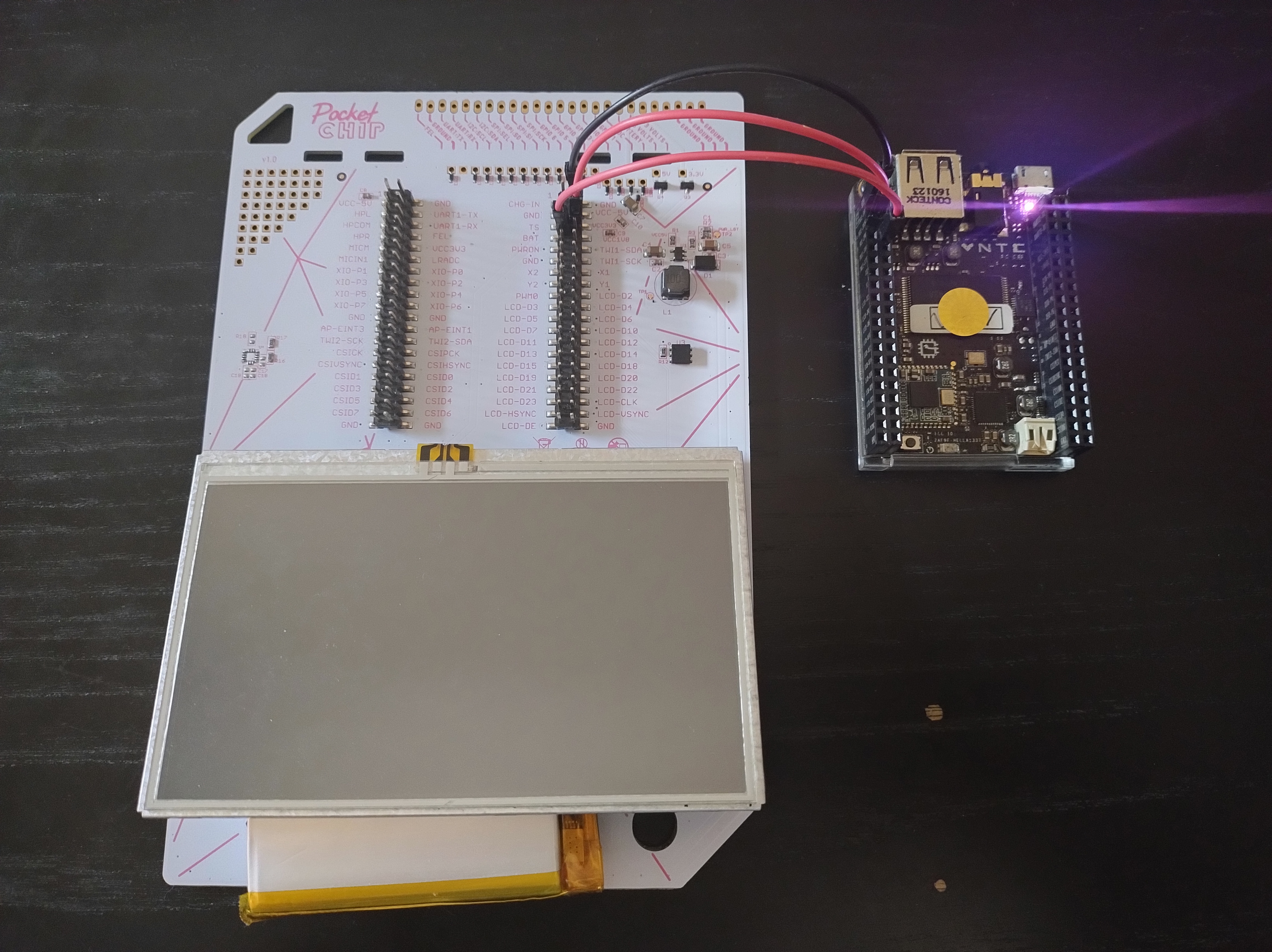
To test, I set up the screen so that it’s on the same side as the pins, and then I connect the CHIP to the board with jumper cables. I’m keeping the battery unplugged most of the time and power the CHIP through a power cable. This is what it looks like:
Some quick testing shows the following:
- With VCC3V3 and GND connected nothing happens3.
- With the pins above, plus LCD-D02, LCD-D10 and LCD-D18, and with the battery plugged in, the display lights up white.
- Without the battery or VCC3V3 the display goes black again.
- Without the battery, but with all other pins above connected and another VCC3V3 from the CHIP connected to BAT on the board, the display lights up white. The CHIP powers off after some time, which might be automatic when it finds no battery is connected (the kernel in use is specifically for PocketCHIP and different from the standalone CHIP’s, so this is a reasonable assumption). I doubt it is because of safety reasons because the CHIP would output current through this pin when charging the battery anyway.
- With the three power pins (VCC3V3, BAT powered via another VCC3V3, and GND), but without the three colour pins (LCD-D* mentioned above), the display is off.
- With the three power pins, LCD-D02 and LCD-D18, the display lights up white.
Now, I don’t know anything about how the display should work and I’m more-or-less making it up as I go, so at this point I feel like I’m missing something obvious again4. All the tests make sense except the last one. How would the two LCD-D* pins be used to power the backlight as well as signaling colour? If they’re digital signals they’re going to be off at least some of the time, so they’re not even consistent sources!
I also figure out that the behaviour is not consistent if I change pins while the CHIP is powered on. Sometimes the display’s backlight stays on even if I remove one of the required connections. This has caused a fair amount of fake results and confusion as well.
In any case, I decide to put these problems aside for now and test the colour pins instead. I plug in the battery and connect BAT on the board to BAT on the CHIP, because I will need the VCC3V3 pin. I leave all the required pins connected and plug in LCD-DE, LCD-VSYNC, LCD-HSYNC and LCD-CLK. I then connect VCC3V3 to each of the LCD-D* pins. The results are:
- D3 to D7 make the display blue. D3 is very subtle, D7 is very blue.
- D10 to D15 make the display green with the same scale as blue, except that D10 is almost unnoticeable.
- D19 to D21 make the display red, same intensity scale as blue.
- Replacing D2 doesn’t lead to any noticeable change, the screen even stays on if I don’t power off the CHIP in-between.
- Replacing D18 also doesn’t lead to changes, except that the screen powers off while changing cables.
And here’s the second revelation.
We apparently have five pins for blue, six for green and five for red.
Could the CHIP be using RGB565 instead of RGB666, with pins LCD-D2 and LCD-D18 providing power?
Even though the naming of the pins obviously implies that they are data pins?
Even though CHIP’s datasheet very clearly states that they are for RGB666 data?
I test this by wiring the board to my RPi instead of the CHIP. The power pins are wired to VCC3V3 and GND (no battery; BAT is VCC3V3 again), and D2 and D18 are connected to any two GPIO pins. When starting up the RPi, the screen is black. I set the pins corresponding to D2 and D18 to output high. The backlight turns on. I set them to output low. The backlight turns off.
Holy shit, I did it.
The rest is straightforward.
I just need to connect the LCD-D* pins to the correct GPIO on the RPi.
To do that I follow the already linked pinout, skipping Red 5-7, Green 6-7, and Blue 5-7.
I also plug in the four sync pins5.
D2 and D18 are plugged into GPIO 26 and 27.
Regarding the driver configuration, there are a couple extra values that we have to set in /boot/firmware/config.txt.
Next to the changes I’ve already made above I add:
dtparam=rgb565-padhi
gpio=26,27=op,dh,pn
The first line ensures that the driver uses the pins I chose (it would be mode 3 in that colorful table in the Raspberry Pi hardware docs). The second sets pins 26 and 27 to output high so that the backlight turns on on boot.
Backlight control
Now that the backlight is on I’d like to be able to adjust the brightness. The current setup is good for a well-lit workspace, but using the device anywhere that’s even slighly darker is uncomfortable. Luckily, the CHIP’s board has a pin available for Pulse Width Modulation, PWM0. The docs even explicitly state that it is used for LCD backlight dimming.
The RPis have specific pins able to perform hardware PWM (that is, we don’t have to control the modulation using software).
You can see them listed here.
I choose pin 18 because I am not using it yet.
This is configurable though; maybe you’ll remember the following fields of the vc4-kms-dpi-generic overlay:
        backlight-gpio          Defines a GPIO to be used for backlight control
                                (default of none).
        backlight-pwm           Defines a PWM channel to be used for backlight
                                control (default of none). NB Disables audio
                                headphone output as that also uses PWM.
        backlight-pwm-chan      Choose channel on &pwm node for backlight
                                control.
                                (default 0).
        backlight-pwm-gpio      GPIO pin to be used for the PWM backlight. See
                                pwm-2chan for valid options.
                                (default 18 - note this can only work with
                                 rgb666-padhi).
        backlight-pwm-func      Pin function of GPIO used for the PWM
                                backlight.
                                See pwm-2chan for valid options.
                                (default 2).
        backlight-def-brightness
                                Set the default brightness. Normal range 1-16.
                                (default 16).
The channel mentioned above can be zero or one, since those are the two PWM channels (PWM0, PWM1) available on RPis.
Each channel has two pins available, as can be seen in the pinout.
So with pin 18 I have to use channel zero.
Also, PWM is pin 18’s function 2 (even though it’s ALT5, the function is 2 as seen in the help for overlay pwm-2chan).
So the parameters end up as follows:
dtparam=backlight-pwm=0,backlight-pwm-chan=0
dtparam=backlight-pwm-gpio=18,backlight-pwm-func=2
I set backlight-def-brightness to different values to no avail.
The way to control the backlight is by writing a value between 0 (fully on) and 15 (fully off) to /sys/class/backlight/backlight_pwm/brightness.
Good candidate for a small script!
Other stuff
At this point I’d consider the display to be fully functional, but there are still some things I would like to take a look at. However, I don’t think they’re doable with my current constraints, so it’s going to be a short section.
First is the touchscreen. It’s resistive, which means that four pins need to be connected: X1, X2, Y1 and Y2. A reading for the X coordinate is taken by applying a voltage from X1 to X2 and reading the voltage output at Y1, which will vary depending on which point of the screen is touched. For Y the process is the same, except the Xs and Ys are swapped. Unfortunately, RPis cannot read analog values, so there’s no way to set the touchscreen up with the components I have. On the bright side I’m not that interested in touch functionality anyway, I’d prefer using a mouse if needed.
The keyboard built into the board is something I also am not keen on using, but just out of curiosity I check how it would be set up. According to one guy on Reddit:
The keyboard is easy, I have a Tiny 2040 microcontroller plugged into the back converting the I2C to USB. https://gist.github.com/theLMGN/52d284355d46e2eb5fb481f8fa1a5f26. Hardware wise, connect GND (top right most pin) to GND (on 2040), VCC3v3 to 3.3v, TWI1-SDA to pin 4 and TWI1-SCK to pin 5, attaching a 1K resistor from 3.3v to both pins.
So it seems the keyboard is using I2C, which is incompatible with DPI (you can also check the pinouts and you’ll see that there are clashes).
Finally, I was able to unplug VCC3V3 and leave only BAT connected for power in.
Wrapping up
All in all the scrapping of the CHIP has been pretty lackluster. I’ve been able to salvage only the display. That’s disappointing since everthing else is just waste at this point. But at the same time I’m excited because I got the screen to work and it is the component I wanted the most. I also learned about DPI and I’m more confident that I could get the screen to work without the CHIP’s board, which was one of the big reasons to start this process in the first place.
I’m considering making some kind of display + RPi combination to carry around along with a bluetooth keyboard as an on-the-go machine. This would involve perfboards and soldering, things I don’t know much about and am excited to learn. But that’s a topic for another day.
TL;DR
You can get the display and backlight to work with a Raspberry Pi, but I haven’t found a way to set up the keyboard or touchscreen without any additional components.
Below are the pins on the CHIP’s board that correspond to each GPIO slot on the RPi. Place your RPi with the GPIO on the right. The first row of the table corresponds to the top two pins of the RPi. So the first left pin of the RPi (3V3) is not connected. The second left pin of the RPi connects to LED-VSYNC on the CHIP’s board, and so on.
| - | - |
|---|---|
| LED-VSYNC5 | - |
| LED-HSYNC5 | GND |
| LCD-D3 | LCD-D12 |
| - | LCD-D13 |
| LCD-D15 | PWM0 |
| LCD-D18 (power) | - |
| LCD-D21 | LCD-D22 |
| BAT | LCD-D23 |
| - | LCD-D7 |
| - | LCD-D6 |
| LCD-CLK | LCD-DE |
| LCD-D4 | - |
| LCD-D5 | LCD-D10 |
| LCD-D11 | - |
| - | LCD-D14 |
| LCD-D2 (power) | LCD-D19 |
| - | LCD-D20 |
Edit your /boot/firmware/config.txt to include the following:
[all]
dtoverlay=vc4-kms-dpi-generic
dtparam=clock-frequency=9000000
dtparam=hactive=480,hfp=5,hsync=30,hbp=10
dtparam=vactive=272,vfp=8,vsync=5,vbp=3
dtparam=rgb565-padhi
gpio=26,27=op,dh,pn
dtparam=backlight-pwm=0,backlight-pwm-chan=0
dtparam=backlight-pwm-gpio=18,backlight-pwm-func=2
Restart, and your display should work!
-
I found
/proc/device-treewhile looking for ways to debugdtoverlays on Raspbian. It proved useful for this as well. ↩ -
The driver is at this point part of the mainline kernel, which means RPis should be able to use it with a custom overlay, but I don’t really want to code one myself at this point. ↩
-
The datasheet specifies a typical voltage of 3.3V, so it should be VCC3V3 that’s needed. ↩
-
Like not plugging in VCC3V3 and GND at the beginning, and being confused why the display didn’t work. ↩
-
Later I checked the datasheet more closely, and it turns out this display doesn’t even use HSYNC and VSYNC. However, considering that my display is not the PocketCHIP’s original, I’m leaving them in in case others need them. ↩ ↩2 ↩3